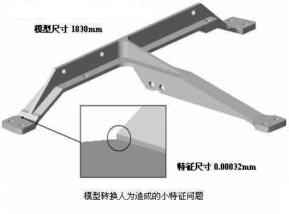
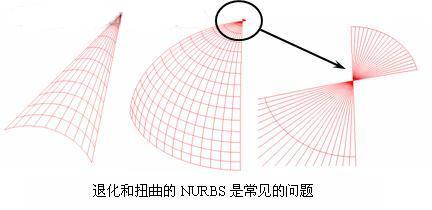
3. Reality The typical real-world question is whether a model fits the actual situation and whether the mesh can be meshed on the finite element analysis. Such problems are usually reflected in the CAD model's feature problems, such as knife edges, slender faces, and internal defects. Cracks and tight faces in the body and body (material thickness tends to 0). The cause of the problem may be the user or the system itself, possibly leaving a thin edge in the physical position misalignment during Boolean operation, or cutting a drilled hole in the cylinder wall due to the extension too far when punching the engine model. Failure of the CAD system can also create real-world problems. For example, the failure of a solid modeling operation may leave a duplicate, a defective entity. The CAD system and the modeling core it is based on have different levels of capability and complexity in terms of tolerance requirements, mathematical descriptions, and geometric complexity. A CAD system that produces high-precision, universal 3D surfaces typically uses thousands of points to define surfaces that are large and time-consuming in model size, and sometimes difficult to use downstream. It is often found that many very complex geometries can be reduced to basic surfaces such as planes, cylinders, cones, and spheres within the tolerances allowed by the acceptance system. Figure 7 shows the allowable tolerance of an over-defined surface. Conditions can be described by a more basic definition. There is also a degree of acceptable readability for the model, which differs in the criteria for distinguishing invalid geometric definitions. One of the most illustrative examples is the technically invalid degenerate NURBS surface generated by three edges, as shown in Figure 8. As shown, some systems can generate such entities, while others refuse to generate. Other systems, although not allowed, generate a distorted four-sided surface in order to prevent such faces from being generated! The other difference in complexity is the coherence of faces and edges, whether it is considered discontinuous in a particular CAD system. A surface may be good in a system, but inconsistencies may be found in downstream systems, resulting in conversion errors or application failures, such as meshing on a discontinuous surface. The difference between today's "tolerance" modelers and other systems is also the origin of the problem. It is possible that an effective model built in a loose system can be completely converted between systems based on the same modeling kernel, once the model is output. Serious problems can be found when you go to a system outside this relaxed environment. In any conversion mode, the data may be misinterpreted and mis-converted. For CAD data conversion standards such as IGES and STEP, they are used differently in all systems. They have their own explanations and vague descriptions. Sometimes it is an incorrect entity, and the system's support for entities under given standards varies widely. So these can cause potential problems in the conversion process, especially in the process of full automation. An excellent metaphor is language translation. If you take an article to three translators, it may be three different articles. They contain the same information. There are more or less translation questions, but no one. Can accurately express the meaning of the original text. In addition to these, a completely automated process always produces 'garbage in – garbage out' situations, and CAD converters have not yet adapted to any other level of intelligence. Basically, all systems differ in some respects, which means there is a high probability of creating synergy issues that arise in downstream applications. Shown about realism, precision, and system-related synergy issues, a simple CAD part seems to be successfully transitioned between the two systems, with no warnings, errors, and failure prompts, and downstream finite element analysts trying to This part is meshed, but it fails, which means that it will take a lot of time to solve this synergy problem. The cause of the problem in this example is that there is a small feature surface (magnified part in the figure) that is most likely caused by Boolean join operations in the original system. This small feature is based on the original CAD system. The tolerance range is perfectly acceptable, while downstream users are faced with how to remove this edge, although acceptable in terms of relative size, but it can cause other situations and cause design intent problems. Previous page next page Steel Pipe,Steel Tube,Galvanized Steel Tube Yongzhong Wiremesh Co., Ltd. , http://www.hbwires.com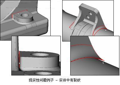
4. System limitations 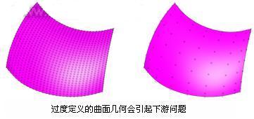
5. Conversion and automation