Butt-Welded Pipe Fittings,Steel Pipe Fittings,Pipe Fitting Jimeng Highstrength Flang-Tubes Group Co., Ltd. , http://www.jmpipefitting.com
Currently, the main tasks of forging technology are to increase the yield strength of the material, extend the life of the mold and apply the net shape forming technology, and apply CAD/CAM/CAE/CAT technology. This article mainly introduces the net formation technology.
The machining allowance for forgings produced by the net forming technology is significantly reduced, which is why it is called the net forming technique. The main purpose of the net shape is to reduce the amount of material, to save some mechanical processing, and to improve the tooth shape strength.
First, the application of net formation technology
1. Input shaft
Compare the tolerances of the selected parts with the cost that can be reduced, and choose to perform a cold extrusion test on the input shaft of the automotive transmission (see Figure 1). 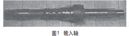
The spline shaft can be extruded in two ways: one is a closed extrusion, that is, no gap is allowed between the material and the mold; the other is an open extrusion, that is, a gap is allowed between the material and the mold. Open extrusion may produce bulging (as shown in Figure 2), the material is completely concentrated between the punch and the die, because the bulging portion has no effective constraint, the bulging, the reduction rate of the section is independent of the mold half cone angle . However, when the extrusion is closed and the elongation of the material is small, cracks may occur (as shown in Fig. 3). 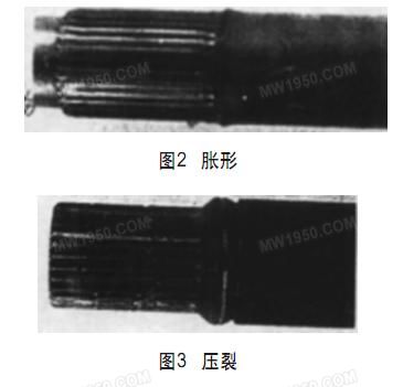
Figure 4 shows the geometry of the three mold inlets: boat, spear, and cone. The tapered mold inlet may produce the largest bulging shape. Using one of the boat-shaped mold inlet or the spear-shaped mold inlet, the splined tip has the best forming performance and eliminates the rotation of the shaft. 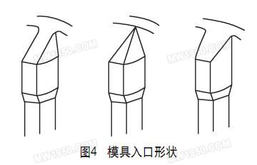
In practical applications, some limitations of the mold inlet geometry are also considered. Therefore, appropriate molding methods and conditions must be selected in a suitable solution.
The production equipment is a 600t vertical three-way five-station automatic press designed by Tiantian Co., Ltd., with a maximum productivity of 30 times/min. The input shaft parts are made of SCr420H alloy steel (Japanese standard) finished rolled round bar. In order to accurately control the weight of the bar, the band saw is used for shearing, spheroidizing annealing, and lubrication before cold forging.
The cold forging process consists of 5 steps. The first two steps are squeezing to complete the top and bottom of the input shaft. The third step consists of squeezing the top and bottom and the pre-thinning intermediate part. The fourth step is the spline shaft tip treatment, and the fifth step is the flower. The key is extruded. Figure 5 shows the cold extrusion process. All five work steps were carried out continuously on a press without any heat treatment and relubrication in between, with a productivity of 20 times/min. 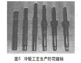
For the extruded spline tooth profile, the section reduction rate on the upper die at the time of closed extrusion was 23%, and the section reduction ratio on the lower die at the time of open extrusion was 18%. Wrinkling and side underfill can reduce the space by 12% due to deformation of the bulging portion. The spline forming portion is relatively short, and the folding defect can be improved by increasing the section reduction rate.
The top and bottom of the spline must be in contact with the mold to control its longitudinal dimension and reduce burrs, eliminating the need for face machining and deburring. The radial runout of the cold forging teeth is within 0.05 mm, and the radial runout of the teeth after machining heat treatment is within 0.08 mm. Therefore, by controlling the radial runout of the tooth within 0.01 mm, the accuracy of the mold can be ensured. Because of the thermal bulging of the mold, the longitudinal dimension changes, so it is necessary to reserve the margin and adjust the closing height of the press during the production process.
2. Differential half shaft gear
The differential gear is used to drive the differential gear rotational force to the driven gear that connects the wheels. The differential half shaft gear has been machined in the past. Figure 6 shows the forging and machining process of the differential half shaft gear. Figure 7 shows the speed gear half shaft forging. 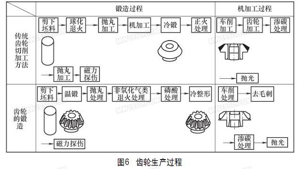

The gears are machined in a conventional manner, and the back and inner surfaces of the gear blanks need to be turned. The Gleason gear cutter is used to machine gears and the turning surface is used as a machining surface. Next is a carburizing treatment in which a hardened layer is formed on the toothed surface. Finally, the back surface of the side gear and the inner surface of the meshing pinion are polished.
In another method, the billet is forged at 900-950 ° C, and the scale is removed by shot blasting. Annealed in a non-oxidizing atmosphere. The phosphating treatment then lubricates to obtain a precise tooth profile, which is cold shaping. The entire gear is inspected on a magnetic defect detector and the tooth profile is coated with a protective layer to prevent rust. The gears are then transferred to a machining line, and the forged tooth profile is used as a machining reference surface to grind the back of the gear. The process after carburizing heat treatment is the same as the conventional method.
Gears with ribs between the teeth can be forged. Gears with ribs reduce the weight and size of the gearbox, and reduce the number of gears from four to two in the pinion drive train, reducing costs. However, since the trajectory of the tool is interfered, there is no rib between the tooth shapes of the machined gear.
The main performance of the increase in gear strength and cost reduction is as follows: 1 The tooth surface accuracy of the forged gear and the machined gear is equivalent. 2 can meet the strength requirements of the transmission box. 3 products have sufficient precision and strength.
3. High clutch hub
The high clutch hub is a part of the automatic transmission. This part consists of two parts, a high clutch hub and a conductive hollow shaft. The purpose of developing new parts is to reduce the number of parts and reduce the assembly cost. Another reason is to reduce the machining process through the net forming technology, which saves a lot of product design to the actual production time. Figure 8 shows a comparison of manufacturing a high clutch hub using conventional and new methods. 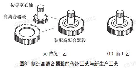
There are several tasks in the development of this process. First of all, it is the dimensional accuracy of the product. To solve this problem, we need to choose the best process design and mold structure. Second, it is the strength of the product, which can increase the hardness of the spline by changing the dimensional tolerances and the composition of the material. Finally, how to extend the die life of hot forging dies can improve die life by optimizing mold structure and mold materials.
4. Driver disk
In the past, the formation of sheets could not control the thickness of the sheets, but it has been greatly improved in recent years. The spinning process makes it easy to control the thickness of the sheet. By optimizing the distribution of the thickness of the part of the material, the thickness feature is used to control the reduction of the weight of the part, and the combination of the two different thickness parts reduces the production cost and the weight of the part. Usually, the raw material of this process uses a thin plate, however, the forming mechanism is similar to that of forging, and a large amount of material flow is formed.
Compared to press working, the spinning process saves a lot of investment in molds and equipment. In addition, although the productivity of the spinning process is lower than that of the press processing, the spinning process can produce small-volume parts at low cost and is easy to assemble a production line, and thus the application is more and more extensive.
Figure 9 shows the integrated drive disc. Since the edge has a thick tooth, the drive disc is punched out by the punching process and then the ring is welded together (the process flow is shown in Figure 10). 
Figure 11 shows the forming process of the part. With a new deformation method, the thickness can be increased without wrinkles. The entire manufacturing process includes blanking, stamping and spinning to increase the thickness, the spinning process is used to form the toothed portion, and then high frequency induction hardening, the entire process consists of a continuous production line. The new production line reduces costs by 30% and reduces the time required from product design to actual production by 80%. 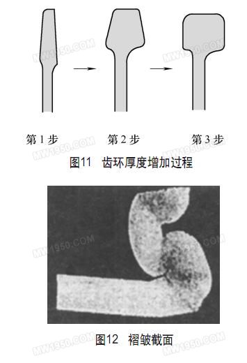
It has been reported that another method is to use the blank to wrinkle during the stamping process to increase the thickness, but considering the yield strength of the part, this method is limited to the case where the wrinkle defect is within the allowable range (as shown in Fig. 12).
Recent developments have shown that the rotating wheel moves from the outside to the inside of the disk, thereby changing the volume of the material, making the disk shape into a shaft shape (as shown in Fig. 13). This new process makes a variety of different parts an integral part. 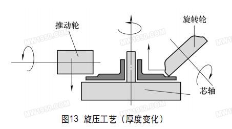
Further reports indicate that hot forging and spinning processes can be combined when producing large deformed parts. The new forming process includes a cup-shaped portion of the hot forged part and a toothed portion of the inner surface of the spin-formed cup. This process can also reduce costs.
5. Outer seat
The formation of a spherical groove on the outer race can eliminate roughing or even finishing, and is formed by precision forging. This technology has the following characteristics:
(1) EDM is used to optimize the electrode form to improve the forging accuracy.
(2) Optimize the cooling conditions of the induction hardening to make the deformation uniform after heat treatment. Therefore, in addition to the forging process, the development of technology can reduce the investment cost in machining.
Figure 14 shows the groove formation of the outer race. Using the method of Tagnchi, the dimensional accuracy of the final shape is optimized by adjusting the preformed shape, the induction hardening conditions, the material hardness and the material composition. High-precision measurement technology can improve the quality of precision molds and products, and precise electromachining technology can also process precision molds through electrical discharge. 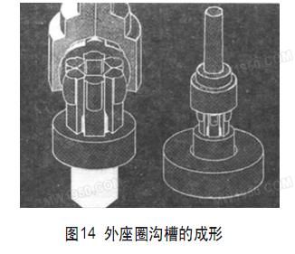
Second, the application of CAE in net formation
Split-forging technology for helical gears is a popular new forging technique. We performed a computer simulation of this new forming process and used the feasibility of the Taguchi method to optimize the simulation process parameters and die size. First, the contours of the helical gear are obtained by comparing the results of the test and simulation. The simulation parameters are adjusted to narrow the difference between the test and the simulation results, and these differences can be reduced by adjusting many parameters and friction factors.
The target component known as the "main gear" is an integral part of the automotive transmission and is a helical gear at the periphery of the transmission. The split method includes three cold processes. The first process is upsetting; the second process is to replace the original mandrel with a thinner mandrel during the first splitting process; the third process is to use the model boss to split the second (as shown in Figure 15). ). All processes are carried out until the forming load reaches a certain value. 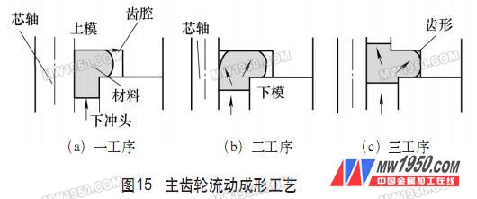
To fill the tooth shape, two main mold design parameters were selected. The simulation calculates 25 steps and obtains the distribution of the fill in the two-parameter model. The optimum combined diameter of the mandrel and the split hole is obtained by the feature surface method and the optimization method.
Third, the conclusion
(1) Spline shafts, differential half shaft gears, transmission parts, drive plates and constant velocity joint parts are manufactured by forging technology. In particular, from the perspective of automated manufacturing, the goal of the effort has been clarified to promote the development of related technologies and to improve the performance of these automotive parts.
(2) Summarize the future tasks of cold forging and warm forging, and improve related auxiliary technologies. Developed a steel for cold forging that can withstand large deformation in steel. Due to the complex shape during warm forging, this steel will expand the application range of the cold forging process. In the field of cutting and blanking, high vertical precision cutting edges and uniform weight cutting tools are being studied. The focus of improvement as a mold material should be to improve high temperature and wear resistance.
(3) In addition, the optimized composite forming technology adopts a composite forming process or a separate cold, warm, and hot forging process. When a net shape is applied to a particular shape, the composite process is more suitable, standardization is necessary, and the 3D simulation tool and the Taguchi method are very effective in reducing the optimization time.
Considering the current form of the forging process, further efforts are needed to reduce the process cost and increase the added value (such as the net shape application), and compared with other forms of production methods, the development of auxiliary technology is also very important for the practical application of the forging process. In addition, the application of machining, heat treatment, parts inspection, tool manufacturing, digital engineering and other technologies should be greatly improved.
A forging factory in Japan produces many types of forgings. The forging process is divided into hot forging, warm forging and cold forging according to the forging temperature. The weight percentages of forgings produced by these three methods are 80%, 8%, and 12%, respectively. Typical hot forgings include crankshafts, connecting rods, constant velocity steering pin, hub and gear blanks. Cold forgings mainly include inner race, cross shaft, input shaft and pinion shaft. Warm forgings mainly include outer races, bushings, side gears and meshing pinions.