Numerical Simulation of Pneumatic Field of Computational Axisymmetric Jets Hu Guoqing Liu Mingyu 2, Fu Dexun, Ma Yanwen 21.1 Institute of Mechanics, Chinese Academy of Sciences, Beijing 1000802, China. Institute of Mechanics, Chinese Academy of Sciences, Beijing 100080, China, constructed a magical 1st, 0 integral and calculated phase Combined with the algorithm, the high-precision difference format is used to numerically simulate the axisymmetric jets of different nozzle Mach numbers, and as the near-field sound source, the far-field aerodynamic noise is studied by the illusion stop and integral method. The numerical result fox far-field noise has directionality, and the noise sound pressure reaches the maximum value away from the symmetry axis 20. As the propagation distance increases, the noise directivity gradually decreases. Consider a closed surface of 1 that is determined by Equation 0 and specified as the exterior of the surface. A challenging lesson. Among the many noise sources, jet noise from jet engines is the most prominent key. Experimental research shows that the jet shear motion electroacoustic source is mainly dominated by large-scale coherent structures. The energy of the subsonic jet noise mainly comes from the nozzle to the downstream 4,5 times the diameter of the region 41. The experiment of 13,65 observes that the far-field noise of the jet has a strong directivity, that is, the noise distribution and the area where the observation point leaves the exit diameter of the jet main shaft, which is the transition stage of the shot loss stable large-scale vortex and the start of transition. Large-scale coherent structures play a leading role in the flow field characteristics. Accurate understanding of the flow field characteristics of the jet at this stage is the basis for studying jet noise. Calculate the combined algorithm and then calculate the axisymmetric compressible unsteady using the 5th order upwind compact format and the 3 scale 1 increase 6 like 3 method. Equation 68, gives the axisymmetric jet flow field under different Mach number conditions, and uses this as the near-field sound source, combined with the 1st, integral formula to study the far-field sound field characteristics. 2, integral and 0 method combined with the basic idea of ​​the 1 claw method is to use a control plane control surface 5 fixed case of the other pass integral unit as the unit normal vector, 0 is the vector sum! The cosine between the directions. The values ​​at the right end of the equation are obtained at the time of the delay time 1 = 纟 77. Thus, by knowing the value of 0 on the control surface and its derivative value, the value of 0 of the far field observation point can be obtained by the equation 1. Acoustic waves from the control surface to the observation point need to be fixed by the Fund Project 1 National Natural Science Foundation 9872069 and 1997-0799032805. Author brief introduction Hu Guoqing 1969, male, Ph.D., mainly engaged in computational fluid dynamics and computational aeroacoustics research. Time, calculated is the discrete value of the different area elements of the control surface. Starting from different area elements, the time when the sound wave reaches the far field and the observation point will be different because of the distance, which needs to consider the influence of the propagation time. If the heart is the distance from the area to a certain observation point, then the propagation will have an effect on the sound pressure of the observation point. In numerical calculations, the concept of a layer can be defined to define ten. , int is a rounding operator. As long as it is small enough, the error of the above formula is negligible. Each area element is =2. Both of the observation points can be calculated using the following formula. Here, day 1 is the sum of the items in the right end of the formula 1, 5; is the area of ​​the area element. In the actual flow field calculation, due to the stability limitation, it is sometimes very small. It is not necessary to perform illusion every step; è¯Žé€ integral, but can be integrated every å°¤ step, then the 3 formula becomes the flow direction here, the factory radial 7 7 is the shear stress such as the heat flux corresponding to the direction of the plant, 7, the density of the fluid, the axial velocity, the radial velocity, the temperature pressure and the unit mass energy. The dimensionless system is 9, V7, 9,079, 3; and, points. The superscript represents the dimension quantity, the subscript, the generation flow, and the characteristic length. The radius of the nozzle is selected in the text. 2.2 Differential Dispersion The convection term in Equation 5 is 51686, and after 1 minute, 71, the 5th-order upwind compact format is removed from the viscous term with a 6-step pay-for-tight format. A few bodies can participate in the text 8. Time to promote the use of 3 less 3 orders of the celestial method. 2.3 Boundary conditions and initial conditions The upper boundary and the exit boundary adopt the non-reflective boundary condition. In the symmetry axis of the jet, ie 〃=0, the symmetry condition is adopted according to the physical characteristics of the flow, and the antisymmetric condition is adopted. The numerical physical flow is calculated as the speed of the jet and = from 0.8 into the stationary environment medium and mixed at the same temperature 5. The initial conditions are calculated as follows. The calculated area has an axial length of 6 and a radial direction of 8.25 with a non-uniform mesh, so that the grid spacing is the closest in the vicinity of the factory=1, and the grid point number boundary is given the inflow condition. In order to make the flow as fast as possible; Kunsuke creates a vortex pair, and superimposes the artificially disturbed 2-axis symmetric jet flow field at the entrance to calculate the governing equation. The axis-symmetric compressible jet is governed by a cylindrical coordinate tube, where 2.4 the jet flow field Calculate the sequence of results, from top to bottom, the growth interval is 4. From 2, it can be seen that due to the artificial disturbance added by the inlet boundary, in the early stage of jet development, the jet begins to produce wavy motion, then roll up and form an independent Human scale vortex. After the large-scale skin vortex falls off and the downstream soul is affected by the harmonic interference, the adjacent two vortices are close, and the vortex is gradually formed. After and after, the distance between adjacent vortices is increased by a factor of two. From 2, the convection velocity of the large eddy is also 1.06, and the velocity is basically kept at no interval. The 4 contours are from 2.8 to 2.8, and the interval is very consistent. 3 is a sequence of jet vortices from =0.8, amplitude 0.15. Since the jet is not easy to be unstable under the higher Mach number, the disturbance amplitude is increased to 0.15 in the calculation, so that the vortex is generated as soon as possible. Compared with the case of 0.4, it seems that the position of the pair is relatively lower. The evolution process of the vorticity at 0.8 is from 0 to 2.8 from the top to the bottom, and the interval is 0.14. The distribution is 0.14 on the semicircular arc with the center of the nozzle as the center radius 100100 and 200. The observation points are distributed at intervals of 10, and the azimuth direction increases from 0 to 180. The near-field adopts a cylindrical surface surrounding the jet flow field as a control surface, 13 is a cylinder length, and the core is a cylinder radius. The sound pressure on the control surface and its derivative value can be divided into 100 grids by the jet calculation, but due to the symmetry, it is only necessary to integrate on the semi-cylindrical surface. The integration time step is taken as 10, here is the advancement time step of the jet near field calculation. According to the position of the vortex, the length of the control surface is taken as 20å²£=0.4 or 30°;=0.8. Using Equation 4, the far-field noise calculation can be performed simultaneously in the near-field calculation process. In the 1. other method, the selection of the control surface has a great influence on the far field noise calculation. Many flows, such as jet wakes, have slow flow attenuation, and it is impossible to obtain a long control plane. The control plane gives a geometric criterion. It is considered that if the connection between the far-field observation point and the near-field main sound source passes through the magic If he controls the surface, then the truncation error will be smaller, and vice versa. Therefore, in order to reduce the truncation error, the radius of the control surface should be as small as possible, and the length 1 should be as large as possible. However, if he is too small, the control plane may not include all the nonlinear disturbances of the near field, so that the linear propagation of sound waves is not guaranteed, which leads to other errors. Therefore, before performing the 1 integral, the reference sound pressure in the calculation formula of the appropriate 3 jet far field sound field must be selected. When the sound pressure is ,, the far field factory = 100 sound pressure machine distribution. It can be seen that the results of 4 and 7=5 are relatively high. It can be considered that under the condition of 4, the radius of the control plane is 45 and the majority of the nonlinear disturbances have been included, and the calculation result is reliable. And 3 at this position caused by a large grid spacing. It should be noted that no matter what value he takes, there is a difference in sound pressure between the two points at 0=, and 018, which is consistent with the previous analysis of the control surface error. The sound pressure at the far field factory = 100 is the maximum at the comparison. The experiment of PCT, 131 also showed that the far field sound pressure of the jet flow reached a maximum around 20. It can also be seen from 6 that the sound pressure at 〃=100 varies greatly with angle, while the sound pressure change at 〃200 is relatively flat, especially in the range of 30 to 140, which shows that the distance increases with the distance. The directionality of noise intensity has a tendency to gradually disappear. At the time, the far field factory = 100 sound pressure muscle distribution. It can be seen that the results of 1=5 and 8=6 are relatively high, while 7=4 and the former two have 5 sound pressures at the far field factory=100, and the parts 1 are compared in the fixed error, and the case like 0.4 Different. This is because the jet Mach number is from; larger, nonlinear disturbance attenuation is slower, and the control plane with radius = 4 does not include all nonlinear effects. This result shows that when calculating the high Mach number jet noise, it is necessary to increase the control plane accordingly. 8 is 7, = 0.8, factory = 100, 200 sound pressure as a function of azimuth. The far field sound pressure 81 reaches a maximum at 0=2. Comparing the corresponding curve 6 from ==0.4, it is found that the far-field sound pressure not only increases the intensity, but also decreases with the azimuth. The sound pressure spectrum at 0.4 and factory = 100, and the number of 31 commits is defined as 57 = 7 feet. As the azimuth angle increases, the sound pressure peak shifts toward the high frequency direction, and the energy distribution range becomes wider. 4 Conclusions Firstly, a method of combining 1 soil integral and 0 method is proposed. By solving the axisymmetric compressible core 6,168 equation, the axially symmetric jet flow field under two Mach numbers is calculated. The far-field noise characteristics of the jet are studied in combination with the integral of one ground. The result is that by superimposing the fundamental frequency and the subharmonic disturbance at the jet inlet, the vortex rolling up and off can be promoted. The pair of vortices in the jet can greatly increase the momentum thickness. The compressibility effect has an inhibitory effect on the growth of the disturbance wave. The selection of the control surface has a great influence on the noise calculation. Under the premise of ensuring that the control surface contains the nonlinear disturbance of the near-field sound source, the radius of the control surface is as small as possible. In this paper, the far-field noise generated by the Ming subsonic jet has different intensities in different directions, that is, there is directionality. The far-field noise has a sound pressure peak near the main flow direction 20, and its directivity is weakened as the propagation distance increases. æ±¾ Reference I7 Fu Dexun editor. Calculate the aerodynamic elbow. Beijing Aerospace Publishing ±,
Stainless Steel
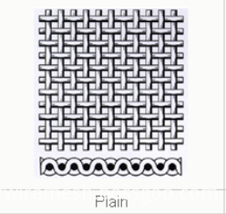
Plain Weave Mesh is one of the most popular Stainless Steel Mesh. Its main
feature in weave type is the same density of warp and weft wire diameters.
Material: 201,304 (L), 310, 316 (L), 410, 430, etc.
Weave
characteristics: Stainless Steel Plain Weave Mesh
is one of the most common way of weaving, the warp and weft are overlapping,
and the warp and weft yarn with the same diameter, the wire along the long, the
net width of weft are parallel to the net, the warp and weft wire cross, one at
the top at the bottom, at an Angle of 90 °.
Properties: acid resistance, alkali resistance, high temperature resistance,
tension and abrasion resistance, good filtration precision and high load
strength.
USE: Stainless steel mesh is widely used in aerospace, petroleum,
chemical industry, scientific research and transportation, etc, used in acid,
alkali environment conditions screening and filter, oil industry as mud mesh,
chemical fiber industry as screen mesh, plating industry as pickling nets
Specification: The standard roll width: 1m-2m. Standard
roll length: 30-50m.
The steel mesh in special width and length
can be produced according to customers` requirements.
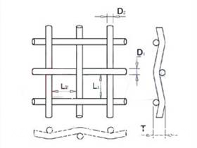
The warp wire (D1) : all longitudinal
braided lines.
The weft wire (D2) : all horizontal weaving
lines.
Aperture (L1 and L2) : the distance between
two meridians or two weft.
Mesh number:number of mesh holes per inch.
Thickness (T) : thickness of the net.
SPEC
WIRE DIAMETER
APERTURE
OPENING
RATE
WEIGHT(POUND)
INCH
MM
INCH
MM
1x1
.080
2.03
.920
23.37
84.6
41.1
2X2
.063
1.60
.437
11.10
76.4
51.2
3X3
.054
1.37
.279
7.09
70.1
56.7
4X4
.063
1.60
.187
4.75
56.0
104.8
4X4
.047
1.19
.203
5.16
65.9
57.6
5X5
.041
1.04
.159
4.04
63.2
54.9
6X6
.035
.89
.132
3.35
62.7
48.1
8X8
.028
.71
.097
2.46
60.2
41.1
10X10
.025
.64
.075
1.91
56.3
41.2
10X10
.020
.51
.080
2.03
64.0
26.1
12X12
.023
.584
.060
1.52
51.8
42.2
12X12
.020
.508
.063
1.60
57.2
31.6
14X14
.023
.584
.048
1.22
45.2
49.8
14X14
.020
.508
.051
1.30
51.0
37.2
16X16
.018
.457
.0445
1.13
50.7
34.5
18X18
.017
.432
.0386
.98
48.3
34.8
20X20
.020
.508
.0300
.76
36.0
55.2
20X20
.016
.406
.0340
.86
46.2
34.4
24X24
.014
.356
.0277
.70
44.2
31.8
30X30
.013
.330
.0203
.52
37.1
34.8
30X30
.012
.305
.0213
.54
40.8
29.4
30X30
.009
.229
.0243
.62
53.1
16.1
35X35
.011
.279
.0176
.45
37.9
29.0
40X40
.010
.254
.0150
.38
36.0
27.6
50X50
.009
.229
.0110
.28
30.3
28.4
50X50
.008
.203
.0120
.31
36.0
22.1
60X60
.0075
.191
.0092
.23
30.5
23.7
60X60
.007
.178
.0097
.25
33.9
20.4
70X70
.0065
.165
.0078
.20
29.8
20.8
80X80
.0065
.165
.0060
.15
23.0
23.2
80X80
.0055
.140
.0070
.18
31.4
16.9
90X90
.005
.127
.0061
.16
30.1
15.8
100X100
.0045
.114
.0055
.14
30.3
14.2
100X100
.004
.102
.0060
.15
36.0
11.0
100X100
.0035
.089
.0065
.17
42.3
8.3
110X110
.0040
.1016
.0051
.1295
30.7
12.4
120X120
.0037
.0940
.0064
.1168
30.7
11.6
150X150
.0026
.0660
.0041
.1041
37.4
7.1
160X160
.0025
.0635
.0038
.0965
36.4
5.94
180X180
.0023
.0584
.0033
.0838
34.7
6.7
200X200
.0021
.0533
.0029
.0737
33.6
6.2
250X250
.0016
.0406
.0024
.0610
36.0
4.4
270X270
.0016
.0406
.0021
.0533
32.2
4.7
300X300
.0051
.0381
.0018
.0457
29.7
3.04
325X325
.0014
.0356
.0017
.0432
30.0
4.40
400X400
.0010
.0254
.0015
.370
36.0
3.3
500X500
.0010
.0254
.0010
.0254
25.0
3.8
635X635
.0008
.0203
.0008
.0203
25.0
2.63
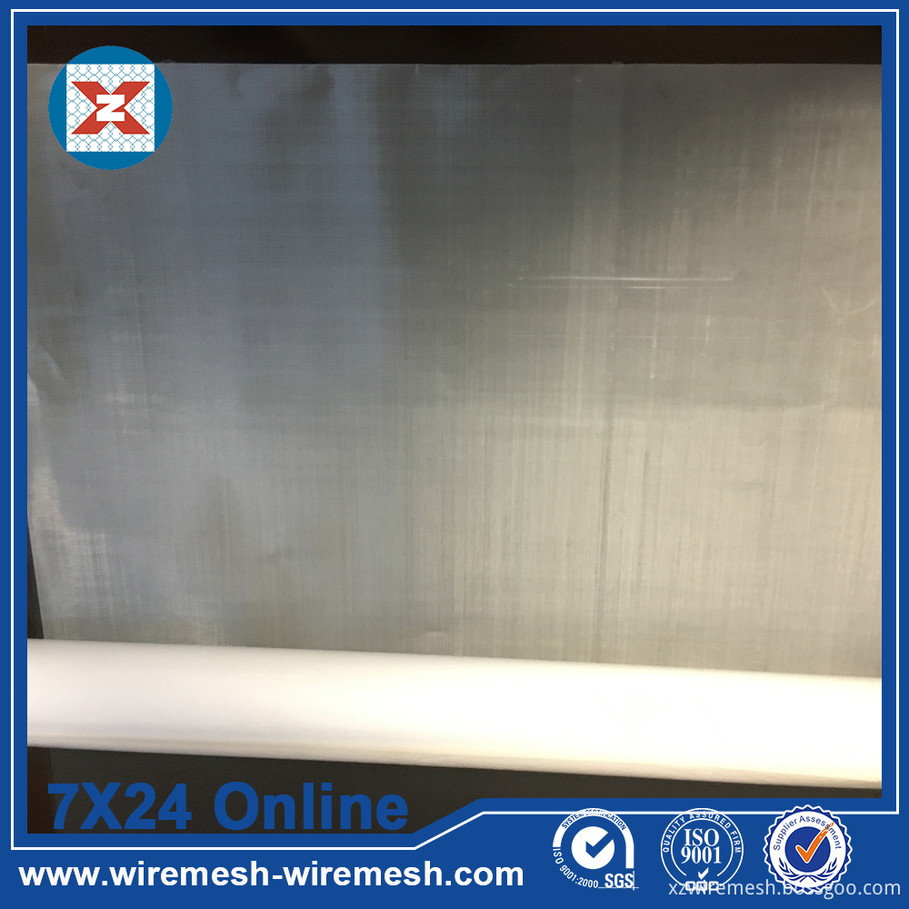
Products Photoes:
Stainless Steel Plain Weave Mesh Stainless Steel Plain Weave Mesh,Stainless Steel Wire Mesh,Stainless Steel Mesh,Plain Weave Mesh Anping Xinzheng Metal Wire Mesh Co., Ltd , https://www.sievingmesh.com

