Steel chimney installation construction plan
Steel Chimney Installation Construction Plan
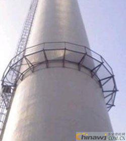
Steel chimneys are widely used in industrial buildings, especially in metallurgical furnace structures, due to their short construction period, minimal material usage, convenient installation, and low labor requirements. The steel chimney for the two-rolling project of Hengyang Hualing Steel Tube Co., Ltd. is a towering structure, standing 74.5 meters tall, with the chimney extending 15 meters above the supporting framework. The inner wall is lined with refractory materials, and the segments are heavy, making it difficult to use large lifting equipment due to limited space. Considering cost-effectiveness, a detailed plan was developed and successfully implemented. Based on practical experience, this method has been refined and optimized. Using this technique not only reduces costs but also simplifies the process, ensuring safety and reliability. It effectively addresses issues related to site constraints and high installation costs, offering significant technical and economic benefits.
1. Key Features of the Construction Method 1.0.1 Simple construction procedures with reasonable process settings and good operability. 1.0.2 Not restricted by site conditions, with economical and reliable lifting equipment selected. 1.0.3 Solves the problem of limited space that prevents the use of large-scale lifting machinery. 1.0.4 The flip-chip method significantly reduces high-altitude work. 2. Scope of Application This method is suitable for steel chimney construction in facilities such as heating furnaces, electrostatic precipitators, and fan rooms. 3. Principle of the Process Except for the first section, which is lifted by a crane, all other sections are installed by placing the pole on top of the previous section. Once installed, the pole is moved up and secured for the next segment. This cycle continues until the entire tower is erected. The tower serves as a lifting point for each section, and the chimney is completed using the flip-chip method. 4.1 Tower Installation 1) The tower is installed in sections based on its length, structural characteristics, and site conditions. It is divided into three parts (seven sections total) with flange connections. - First part: 508×10mm spiral tube, 16,768mm long, split into two sections (11,000mm and 5,768mm). - Second part: 325×8mm seamless tube, 20,772mm long, split into three sections (7,750mm, 8,000mm, and 5,022mm). - Third part: 203×6mm seamless tube, 18,139mm long, split into two sections (10,000mm and 8,139mm). 2) Based on the center point provided by the foundation unit, re-measure and mark the central target board for future verticality checks. Verify the foundation flatness before proceeding. 3) The first section of the tower is installed using a 16–25-ton truck crane. A 16mm directional twisted steel wire rope is tied to a fixed pulley on the tower, serving as the lifting point for the pole. The hoist lifts the pole to the designated position for the second stage. 4) According to the "Practical Building Construction Manual," the single pole is typically made from 159–426mm seamless steel pipes. The upper tower section is 16m long, 168×10mm, with 50mm or larger angles welded at 1/3 of the mouth. Four 3-ton fixed pulleys are installed at the base for the main and swing control systems. Ropes are used to prevent displacement during lifting, and the pole is securely bound to the main tower. A 3-ton guide pulley is installed at the bottom, while a fixed pulley is placed 8 meters from the base to control swing angle. Two wind ropes are added for stability. 5) The lifting points are generally located at 2/3 of the pole’s height, with a maximum weight of 670kg. After installing the main pole, crossbars and supports are added through scaffolding or ladders. Each section must be checked for alignment and corrected if necessary. 6) After completing the second tower, move the pole to the next position and repeat the process until the full structure is installed. 7) As the tower is built upward, peripheral scaffolding is erected alongside, and the design ladder is used for welding between sections. 8) Flange connections must be concentric, with bolts freely passing through. Ensure tight connections and parallel flanges. Verticality error between the main rod and flange should not exceed 2mm. 9) Welds must meet third-level weld requirements, and rib joints must meet second-level standards, with magnetic particle inspection conducted. 10) Use the tower rail to measure the center point of each layer and check verticality with a theodolite. The overall vertical deviation should be ≤H/2500 + 10mm, with a maximum of 32mm. 11) At 55m height, after all internal structures are welded and inspected, perform self-inspection, mutual inspection, and special inspection before proceeding with chimney installation. 4.2 Chimney Installation 1) The chimney is installed in two parts: - First part: -4.5m to -0.5m, installed with a 16–25-ton crane. Check cylinder center and ellipticity. The base flange is assembled and welded at -4.5m. - Second part: -0.5m to +70m, installed using splicing and flipping. Three sections: +36m to +70m (34m), +11.5m to +36m (24.5m), and -0.5m to +11.5m (12m). 2) Two sets of 10-ton pulleys (3×3) are used on the 55m tower. A 16mm steel wire rope is used for lifting, with the main pulley block fixed on the tower top. The first chimney section is sent to the tower center, then moved horizontally to align with the previous section. Positioning cards are evenly welded inside the cylinder, and the upper section is lowered and aligned. After assembly, it is temporarily fixed to the tower. 3) When the chimney reaches 55.5m, install and weld the chimney cap and ladder. Raise it to 71.5m and secure with three 25mm wind ropes to prevent swinging. 4) After the last section is installed, positioning cards are welded on the inner wall of the buried section. The third section is returned and welded. Measure verticality with a theodolite, use chain hoists for leveling, and ensure each joint does not exceed t/3 (t = wall thickness). Control the vertical deviation of the chimney to H/2500 + 10mm, ≤38mm. 4.3 Chimney Inspection After installation, conduct self-inspection and mutual inspection of all welds and submit for review. 4.4 Refractory Insulation Construction 1) Install angle steel ∠100×63×8mm every 5 meters as an inner ring during the chimney fabrication. 2) If conditions allow, install refractory and insulation materials first, then lift them together with the cylinder. If not, use cages for personnel and equipment. 3) Follow product specifications for bonding aluminum silicate fiber felt to steel plates and flue gas surfaces. 5. Labor Organization The project requires multiple types of workers, deployed according to the project schedule. There are 11 construction workers, including one crane operator, one riveter, one high-pressure welder, one ordinary welder, one electrician, and four assistants, plus one manager and one on-site technician. 6. Quality Assurance Measures 6.0.1 Establish a quality assurance system involving management, technicians, and workers. 6.0.2 Conduct thorough reviews of construction drawings, develop operation plans, and ensure quality and technology. 6.0.3 Strengthen technical management and quality inspections, conduct self-inspections, mutual inspections, and special inspections. 6.0.4 Ensure all components are installed and accepted according to design and GB50205-2001. 6.0.5 Collect and organize technical data to ensure accuracy and timeliness. 7. Safety Production Measures 7.0.1 Wear full safety gear during high-altitude work, and secure seat belts to solid points. 7.0.2 Only use operating platforms, ladders, and scaffolding after passing inspection. 7.0.3 Ensure sufficient lighting and lightning protection for aerial work. 7.0.4 Stop work in severe weather (wind over 6, rain, snow, fog) and cut power. 7.0.5 Assign a supervisor during lifting and ensure clear instructions. 7.0.6 Ensure lifting machines are grounded, tested, and maintained. 7.0.7 Maintain at least three turns of wire rope on the reel, and secure the end. 7.0.8 Equip lifting cages with limit switches, stroke indicators, and electromagnetic brakes. 7.0.9 Install anti-rope-groove devices on pulleys and inspect regularly. 7.0.10 Keep acetylene cutting operations at least 10m from oxygen cylinders and 30m from flammable materials. 8. Technical and Economic Benefits This method is simple, cost-effective, and fast. Compared to large lifting equipment, the unit price per ton is 700 yuan/t, versus 1,500 yuan/t for large machinery. For a total weight of 220 tons, this saves 17.6 million yuan. It solves the issue of large equipment being unable to operate on site. 9. Project Example In the Yantai Steel Chimney Project, due to limited space, large machinery could not be used. The steel chimney was installed using this method, achieving excellent technical and economic results. It has proven to be safe, efficient, and cost-effective, meeting engineering quality requirements.
LED Downlight
LED downlight ,with LEDER technology's smooth design is an enhanced and modernized retrofit light. Using a secure and reliable installation method, this light is compatible with housing that features interior spring bracket holders.
Built with steady dimmable technology, and compatible with most modern dimmers including wireless systems. LED Downlight is an especially good choice for anyone looking for a lamp which is elegant in an understated way. If you want an LED Downlight that discreetly keeps itself out of the way, yet looks great once you actually pay attention to it, you have definitely come to the right place. This LED Downlight will do its job very well.
Features:
• Grace design
• Easy to install
• Excellent power saving
• Suitable for operation at low temperature
• Color temperature :3000K-6000K
• Body color can be customized as RAL Code
• Type of protection: IP20 / IP65 (Some models)
• Warranty: 3 ~ 5 years
Our Downlight is compatible with dimmer switches, so you can always get just the right light for dinner or game night. Bring effortless light into your kitchen, bathroom, or living room with this.
We have rich production experience in lighting.Except LED Downlight , we also offered other product in Indoor Lighting .Such as :
LED Panel Light , Track Light , Linear Light ,Wall Light , LED Strip Light , LED Tube Light , Cabinet Light , LED Bulb , LED Ceiling Light as so on .
Recessed Downlight,LED Recessed Downlight,Halo Ultra Thin Downlight,Surface Mounted Downlight
LEDER LIGHTING CO.,LTD , https://www.lederlight.com